
Ring Spinning Frame Components: Spindle, Ring, and Traveler


The three coupled components of a ring spinning frame are a steel spindle rotating at 15,000 to 25,000 RPM inside a fixed 36 to 50 mm diameter ring, a pressed-steel or nylon traveler of 30 to 80 mg that rides the ring at 30 to 45 m/s peripheral speed, and a ring rail that traverses the cop build at 2 to 6 mm per spindle revolution, and together they convert drafted fiber strand into a packaged twisted yarn at delivery speeds up to 35 m/min.
The traveler is the only consumable in the trio and sets the upper economic speed limit of the whole machine, because once peripheral speed exceeds about 45 m/s the wear rate and the yarn tension in the balloon both rise sharply and the end-break rate climbs past economic tolerance.
The sections below cover the bearing design that supports 25,000 RPM, the geometry and metallurgy of ring and traveler, the spindle drive, the ring rail and builder motion that shapes the cop, and the automation layers that doff and replace travelers on modern frames.
Spindle Design: Shaft, Bolster, and Bearing System
The spindle is a vertical steel shaft that carries the yarn package, inserts the twist, and provides the rotational reference for the traveler. A modern short-staple spindle has three concentric assemblies on a single axis: the wharve (drive pulley) at the base, the bolster and blade in the middle (with a yarn-locking catcher), and the footstep bearing at the bottom.
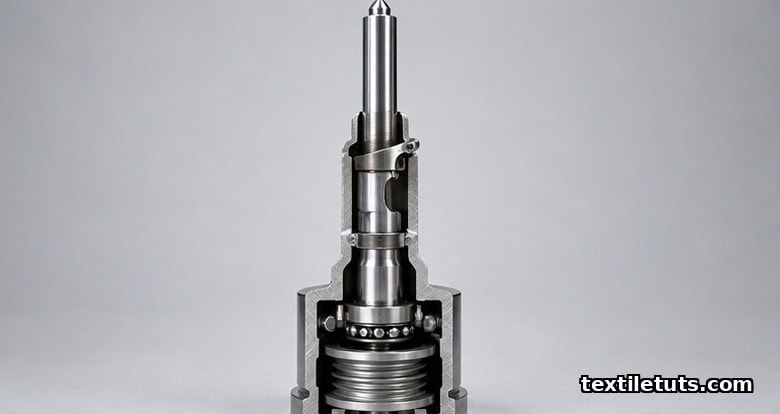
Bearing design limits top spindle speed. Sealed grease-packed bearings, standard on compact frames, support 20,000 to 25,000 RPM. Oil-lubricated bearings are limited to about 18,000 RPM by heat and oil mist. Direct-drive individual-motor spindles decouple the spindle from the line shaft and allow each spindle to ramp, coast, and reverse independently, essential for automated package transfer.
The Ring: Geometry, Material, and Fit to the Frame
The ring is a circular steel track, fixed to the ring rail, around which the traveler runs. It is the stationary component of the twist-insertion system and the datum against which the traveler is loaded by the yarn tension in the balloon. Ring geometry is described by two dimensions: inner diameter (the nominal ring size), which governs the cop build diameter and runs 36 to 55 mm for short-staple cotton and 60 to 90 mm for worsted long-staple frames, and flange height, usually 5 to 8 mm, which prevents the traveler from flying off at high speed.
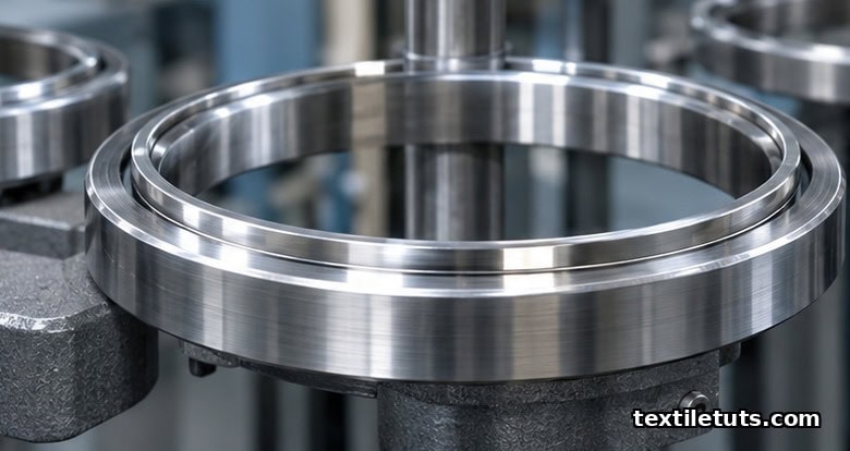
Ring material is hardened bearing steel (typically 100Cr6) with a running track that is either polished to a mirror finish (for steel travelers) or micro-grooved (for nylon and PU travelers). Surface hardness is 62 to 64 HRC, and rings are case-hardened to retain that hardness after years of traveler abrasion.
Ring size is dictated by the frame gauge and the yarn count. A 70 mm gauge cotton frame accepts rings up to 50 mm diameter; a 60 mm gauge compact frame accepts rings up to 42 mm. The traveler on one spindle must clear the adjacent spindle’s ring, and that clearance, plus the ring flange, fixes the maximum ring size for a given gauge.
The Traveler: Shape, Weight, Material, and Speed Limits
The traveler is a small C-shaped clip that rides around the inside of the ring and is dragged by the yarn. The traveler converts the linear tension of the yarn into a tangential load on the ring track, which (combined with the centrifugal load from its own mass) keeps it pressed against the ring and inserts twist.
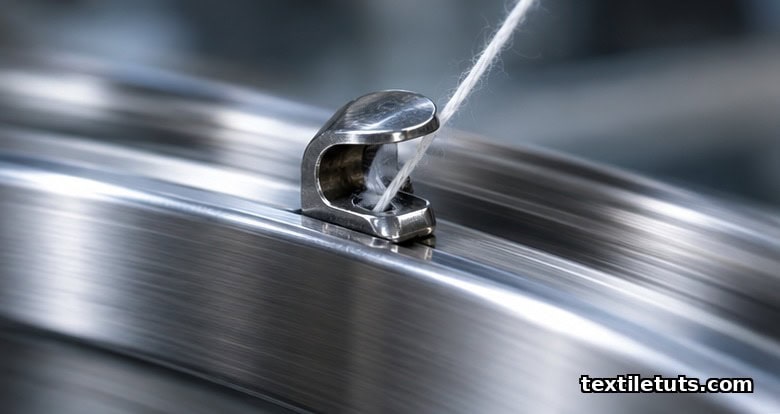
Traveler geometry is described by three numbers: shape (a vendor code indexing elliptical 1/0 to 4/0, flat-top R/RF, or curved-shoulder C/CC profiles), weight (30 to 80 mg for cotton counts up to Ne 60, 80 to 200 mg for coarse and worsted counts), and material.
Three traveler materials dominate. Pressed steel (bright or nickel-finished) is the workhorse for cotton counts up to Ne 50 at speeds up to about 35 m/s. Nylon and PU travelers are used for fine counts and high speeds, run cooler, and tolerate speeds up to about 45 m/s, but wear faster than steel. Ceramic and cermet travelers are premium products for worsted and technical yarn where lint contamination must be near zero.
Traveler peripheral speed (m/s) equals pi times ring diameter (mm) times spindle RPM, divided by 60,000. For a 42 mm ring at 18,000 RPM, traveler speed = 39.6 m/s, near the steel-traveler ceiling. For a 38 mm ring at 25,000 RPM, traveler speed = 49.7 m/s, beyond steel tolerance. Steel travelers last 4 to 12 days at 35 m/s; nylon travelers last 2 to 6 days at the same load.
Spindle Drive and Power Transmission
Two drive architectures dominate modern ring frames. The traditional line-shaft belt drive uses a single motor and a frame-length shaft, with belts looping to each spindle wharve. The modern standard, individual-motor direct drive, places a small motor under each spindle wharve, controlled by a frame PLC, decoupling the spindles and enabling automated doffing and per-spindle data capture.
A modern short-staple ring frame with 1,200 spindles at 20,000 RPM draws 35 to 50 kW (about 30 to 40 W per spindle), of which 60 to 70% is consumed by the traveler-ring friction. Spindle speed regulation must hold RPM within about 1% of setpoint, because a 1% speed error at 20,000 RPM changes twist by 1%.
Ring Rail Motion and the Builder: How the Cop Is Shaped
The ring rail (the carriage that carries the ring and the traveler) moves up and down at a precise rate synchronized with the spindle rotation. This builder motion winds the yarn onto the cop in a stable, doffable shape. It is described by four parameters: lift length (about 180 mm for a 200 mm cop), number of layers (10 to 16 doubles for a typical cotton cop), wind angle (8 to 14 degrees), and step (0.4 to 0.8 mm).
The cop is built in three zones: the base cone where the yarn tail is anchored, the cylindrical barrel where the package gains most of its volume, and the tapered nose cone shaped to release cleanly at doffing. Ring rail motion is generated by a cam-and-lever mechanism or by a servo-driven linear actuator, and servo-driven builders allow quick changeover between yarn counts without changing cams.
Automation: Doffing, Travelers-on-Demand, and Data Capture
Modern ring frames carry four automation layers. Automated doffing uses a robotic arm that transfers a full cop to a bobbin transport and starts a new bare tube (30 to 90 second cycle). Travelers-on-demand uses a small dispenser at each spindle to replace a worn traveler automatically. Yarn-clearer integration feeds each spindle into an electronic clearer that cuts and ties the yarn at thick and thin places. Per-spindle data capture records RPM, doff cycles, traveler changes, and clearer cuts for predictive maintenance.
These layers bring labor cost per spindle from 1 operator per 200 to 400 spindles on a manual line down to 1 operator per 1,000 to 1,500 spindles on an automated line, and raise spindle utilization from 80 to 85% to 92 to 96%.
Comparison Table: Spindle Speed and Ring Diameter by Yarn Count Range
| Yarn count range | Ring inner diameter (mm) | Spindle speed (RPM) | Traveler speed (m/s) | Traveler weight (mg) | Traveler material |
|---|---|---|---|---|---|
| Coarse cotton (Ne 6 to 16) | 50 to 55 | 12,000 to 16,000 | 31 to 46 | 60 to 80 | Pressed steel |
| Medium cotton (Ne 20 to 36) | 42 to 50 | 16,000 to 20,000 | 35 to 45 | 45 to 70 | Pressed steel or PU |
| Fine cotton (Ne 40 to 60) | 38 to 42 | 18,000 to 22,000 | 36 to 45 | 35 to 55 | PU or nylon |
| Compact cotton (Ne 50 to 100) | 36 to 40 | 22,000 to 25,000 | 42 to 48 | 30 to 45 | Nylon |
| Worsted (Nm 24 to 60) | 70 to 90 | 8,000 to 13,000 | 31 to 61 | 100 to 200 | Pressed steel |
Frequently Asked Questions
Q1: What sets the upper speed limit of a ring spindle?
The upper speed limit is set by the traveler peripheral speed on the ring, not by the spindle bearing. Above about 40 m/s with steel travelers or 45 m/s with nylon and PU travelers, the centrifugal load on the traveler and yarn tension both rise sharply and the end-break rate climbs past economic tolerance. Mills push top speed by reducing ring diameter and pairing it with lighter nylon or PU travelers.
Q2: Why are rings made of hardened steel rather than ceramic?
Rings are hardened steel because the wear pair is consumed in a controlled way: the soft traveler wears against the hard ring, and the ring lasts years. A ceramic ring would invert the wear pair and ring replacement would become a routine cost. The exception is specialty rings for worsted and technical yarn, where ceramic coatings are applied to the steel substrate.
Q3: How often must travelers be replaced on a ring frame?
Steel travelers on a cotton frame at 35 m/s typically last 4 to 12 days, depending on yarn count and lint load; nylon travelers last 2 to 6 days. Mills target 0.05 to 0.20 travelers per kilogram of yarn for steel and 0.30 to 0.80 for nylon. Travelers-on-demand systems cut consumption 10 to 25%.
Q4: Can ring spinning reach higher delivery speeds without raising traveler speed?
Yes, by switching to a twist-insertion system that does not rely on a traveler. Rotor, air-jet, and vortex spinning insert twist without a traveler and run at delivery speeds of 100 to 250 m/min. The trade-off is yarn structure: those systems produce yarn with different surface, strength, and hairiness profiles, so ring spinning remains standard where yarn quality is worth the lower delivery speed.
References
- International Organization for Standardization. ISO 2061:2015 Textiles: Determination of twist in yarns: Direct counting method. iso.org. Reference method for TPM measurement.
- Klein, W. The Rieter Manual of Spinning, Volume 4: Ring Spinning. Rieter Machine Works, Winterthur. Industry-standard reference for ring frame spindle, ring, traveler, ring rail, and builder geometry.
- Lawrence, C.A. Advances in Yarn Spinning Technology. Woodhead Publishing (Elsevier), Cambridge. Peer-reviewed coverage of spindle bearing design, ring metallurgy, and traveler friction pair behavior.
- Rawal, A. and Mukhopadhyay, S. Yarn Structure and Properties in Ring, Rotor and Air-Jet Spinning. Textile Progress, Taylor and Francis. Comparative analysis of twist structure and traveler speed limits.
- Oxtoby, E. Spun Yarn Technology. Butterworth-Heinemann (Elsevier), Oxford. Coverage of spindle drive architectures, builder motion, and cop build parameters.
- Uster Technologies. Uster Statistics 2018: The Global Benchmark for Yarn Quality. Uster, Switzerland. Global benchmark for traveler consumption, end-break rates, and CV%.
This article is the working reference for ring frame spindle, ring, and traveler components. Editorial by Iftay Khairul Alam, TextileTuts. Sources: ISO 2061:2015, Klein (Rieter), Lawrence (Woodhead), Textile Progress, Oxtoby (Elsevier), and Uster Statistics 2018 as cited.


