Draw Frame : Functions|Drafting Arrangement|Roller Setting|Autoleveller
What is Draw Frame?
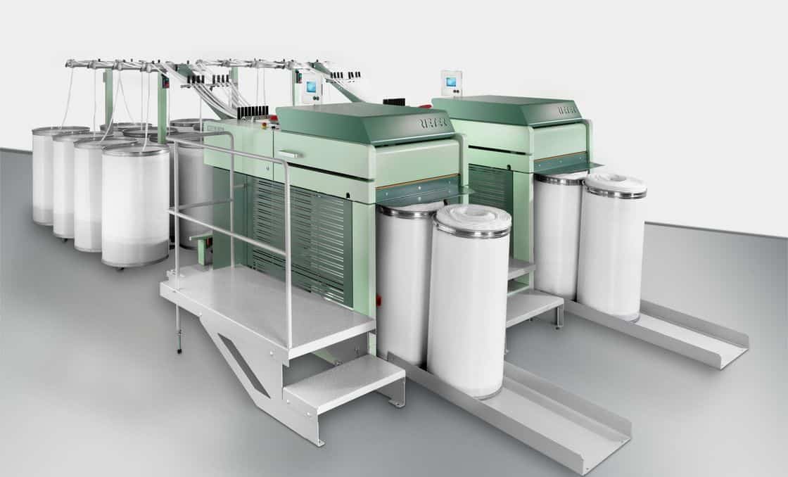
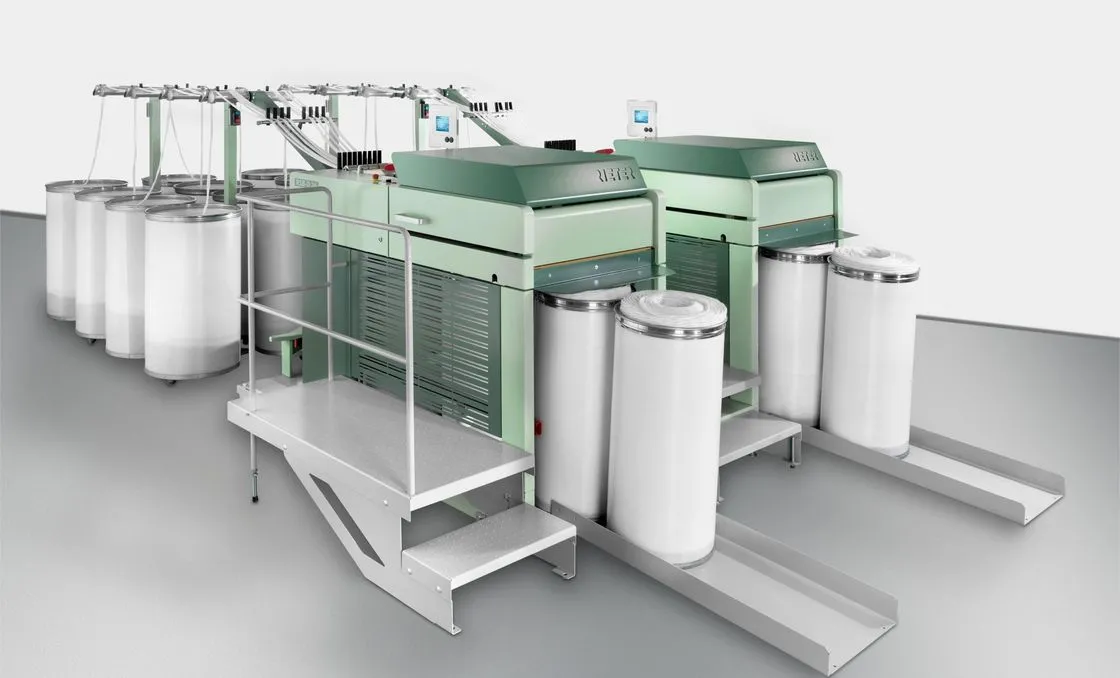
Draw Frame is the machine where slivers are doubled or combined, blended and mixed, leveled, and attenuated through a series of roller pairs. In the drafting arrangement, each pair of rollers moves faster than the prior one.
The key purpose of implementing draw frames in the spinning procedure is to develop yarn quality, particularly yarn evenness, by improving sliver quality. Two draw frames are typically used in the processing of card slivers: the breaker draw frame and the finisher draw frame. In the combing process, these are called the pre-comb draw frame and post-comb draw frame respectively.

Doubling: The practice of merging two or more slivers, roving, or yarns into one. This is not limited to the arrangement of two units only.
Drafting: The process of decreasing the thickness or linear density of the input material by attenuation. Feed supplies may include lap, sliver, and roving.
Drawing: The process of combining and attenuating slivers simultaneously. Drafting without doubling is not optimal for sliver quality, and vice versa.
Drawing = Drafting + Doubling
Functions of Draw Frame
Equalizing
One of the primary responsibilities of the draw frame is refining evenness over the short, medium, and long term. Card slivers fed to the draw frame possess a degree of unevenness that is not acceptable for producing yarn.
Parallelizing
For optimum tenacity in the yarn, fibers must be aligned parallel in the fiber strands through the drafting process.
Blending
In addition to the equalizing effect, doubling also provides compensation of raw material disparity through blending. Diverse fiber types can be combined to achieve a particular blend ratio, such as 65:35 polyester-cotton (PC) or 55:45 CVC blends.
Dust Removal
The draw frame is an effective dust elimination instrument. High-performance draw frames are fitted with proper suction systems that extract more than 80% of incoming dust particles.
Differences Between Carded Sliver and Drawn Sliver
| Carded Sliver | Drawn Sliver |
|---|---|
| The fibers are oriented in all directions. | The fibers are oriented parallel to the sliver axis. |
| Slivers contain leading hook, tailing hook, and both-end hook fibers. | The hooks are straightened. |
| Many fibers project out from the sliver. | Fewer fibers project out from the sliver. |
| Irregular weight per unit length. | More regular weight per unit length due to doubling and auto-leveling. |
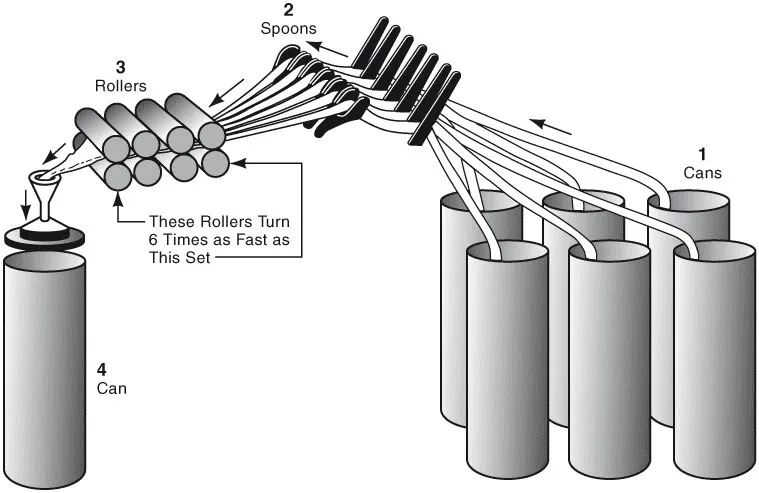
Passage Diagram of Draw Frame
Elements of Drafting Arrangement
The primary elements of a draw frame’s drafting arrangement are listed below:
1. Bottom roller
2. Top roller
3. Top roller pressure
1. Bottom Roller
Bottom rollers are made of steel and driven from the main gear transmission. The types of bottom rollers are:
a. Axial flutes
b. Spiral flutes
c. Knurled flutes

2. Top Roller
Top rollers are not positively driven. They rotate through surface contact with the bottom roller. Top rollers are coated with synthetic rubber. The rubber hardness must be carefully adjusted and is specified in Shore degree.
Soft: 60–70o Shore A
Medium: 70–90o Shore A
Hard: above 90o Shore A
3. Top Roller Pressure
To clamp the fibers, top rollers must be forced at high pressure toward the bottom rollers. The pressure can be generated by the following means:
- Dead weight (now obsolete)
- Spring loaded (the most common form)
- Hydraulic system (rarely used)
- Pneumatic system (Rieter)
- Magnetic (Saco Lowell)
Types of Drafting Arrangement
- Conventional 4-over-4 roller drafting system
- 3-over-4 roller drafting system
- 3-over-3 roller drafting system with pressure bars
- 4-over-3 roller drafting system with pressure bars
- 5-over-4 roller drafting system


Roller Setting
The distance from the center of one roller to the center of another roller is known as the roller setting.
Principles of Roller Setting
- Longer staple fibers require wider roller settings and vice versa.
- Greater bulk of material requires wider settings.
- Faster drafting roller speed requires wider settings.
- Higher degree of compactness requires wider settings.
- Harsh and rough fibers require wider settings because they do not pass through easily.
Drafting Wave
When the sliver passes through drawing rollers, short fibers cause a succession of alternate thick and thin places due to irregular movement. These thick and thin places create a wave on the surface of the sliver called a drafting wave.
The amount of drafting wave depends on:
- The amount of draft
- The roller setting
- The doubling
- The bulk of the material
- Degree of fiber orientation
- Character of fiber
Effect of Doubling and Drafting on Sliver Irregularity
In spinning preparation, correcting variations is undertaken through equalizing, leveling, or averaging effects by doubling at the draw frame. There is only a small possibility that all thin places and all thick places of slivers will coincide during doubling. Rather, they will tend to be distributed and compensate each other.

However, doubling has limitations:
- Doubling averages out only short-to-medium term variations; it does not correct long-term variations.
- It does not correct periodic variations that repeatedly occur side by side.
Doubling reduces the coefficient of variation (CV) value of any occurring variation by the square root of the total number of doublings. At the input to the draw frame, the following law of doublings applies:
CVO = X̄cv / √n
CVO = CV of all n slivers at the input to the drafting elements
X̄cv = mean value of the CV values of all the single slivers
= (CV1 + CV2 + CV3 + … + CVn) / n
n = number of doubled slivers
Example 1: A draw frame is fed with 8 cotton slivers of 4 ktex each. The sum of all CV values of the single slivers CV1 + CV2 + … + CV8 = 22.4%, and the mean value X̄cv is 2.8%. The output sliver irregularity CVO from the draw frame is 2.5%. The irregularity produced by the drafting elements is:
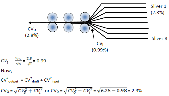
The doubling of fiber assemblies is undertaken primarily to introduce parallelization between fibers and achieve good count constancy between bobbins. However, it offers no possibility of drastically reducing the mean CV value.
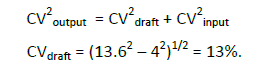
Example 2: The CV of a ring-spun yarn is found to be 13.6%, produced from a roving with a CV of 4%. The CV added by the drafting zone of the ring-spinning machine is:
Autoleveller to Minimize Count Variation of Yarn
Purpose: The reason for applying autolevellers at the carding machine and draw frames is to maintain complete sliver fineness, which ultimately decreases count variation in the yarn.
Function: An autoleveller processes sliver width variations and then constantly adjusts the draft through a servo-controlled drafting system. Additional draft is applied to thick places, and reduced draft is applied to thin places, resulting in a more even delivered sliver.
Classification: Autolevellers fall into three main categories based on their principle of operation:
1. Open-loop autoleveller
2. Closed-loop autoleveller
3. Combined-loop autoleveller
1. Open-Loop System
In this system, there is no measurement on the final sliver. Alterations in draft are established uniquely based on the mass deviation in the feed material. Most modern autoleveller draw frames operate on the open-loop control principle.

2. Closed-Loop System
In this system, checking is completed on the product of the progression, i.e., on the delivered sliver. The closed-loop autoleveller measures the consequence of its own actions.

3. Combined-Loop Autoleveller
This system corrects long, medium, and short-term deviations. Multiple loop arrangements are possible, such as combining an open and closed loop to correct short-term abnormalities with a fast response (open loop) and long-term anomalies (closed loop). Another arrangement combines two distinct closed loops (fast and slow).

A supplementary member of this group combines both open and closed loop features when measurement is completed on material of intermediate thickness between the back and front rollers of a drafting zone. The sliver width at the point of check depends on both the feed and delivered material densities, making this a combined-loop autoleveller.
Start-Up Machine with Autoleveller
Mechanical draft must be chosen appropriately for autoleveller draw frames. To adopt the power-driven draft, the draw frame should be started first with the autoleveller turned off. Gears should be altered so that the sliver weight meets requirements without the autoleveller.
Modern autolevellers correct up to ±25% feed deviation. Standard practice feeds 12% deviation on both the thick and thin sides to check A%. This is called the sliver test. The A% value should not exceed 0.75%. A% is calculated as follows: if the number of slivers fed to the draw frame is N, check the output sliver weight with N, N+1, and N−1 slivers. Then:
A% = {(g/m(N−1) − g/m(N)} / g/m(N) × 100
A% = {(g/m(N+1) − g/m(N)} / g/m(N)} × 100
Advantages of Using Autoleveller
- All types of deviations (short-, medium-, and long-term) are rectified.
- Yarn count CV% remains constant throughout the lot.
- Fewer thin and thick places appear in both the sliver and the yarn.
- Ring frame breaks are reduced.
Rieter RSB Autoleveller Draw Frame (Open-Loop Principle)
The Rieter RSB-D 26 draw frame delivers a maximum speed of 1,200 m/min per head—up to 33% higher than predecessor models depending on fiber material. Instabilities in sliver bulk of up to ±25% are corrected through digital, high-precision autoleveling. Variations in input sliver bulk are sensed by tongue-and-groove scanning discs. Signals are compiled at short, continuous intervals, ensuring very high precision even at maximum speed.

The autoleveling mainframe uses measured signals to calculate the essential speed for the highly dynamic AC servo drive. This calculation is conveyed to the drive precisely when the measured sliver length touches the drafting point in the primary drafting zone. The resultant sliver is free of short-term, medium-term, and long-term abnormalities.
Production Calculation of Draw Frame
Problem 01:
Delivery roller speed = 600 m/min
Sliver Hank = 0.110 Ne
Waste = 0.5%
Efficiency = 85%
Production = ?
Solution:
Production (kg/hr) = (600 × 1.0936 × 60 × 0.85) / (840 × 0.110 × 2.2046)
= 163.74 kg/hr
Problem 02:
Find out the DCP if:
Feed sliver weight = 62 gr/yd
Delivery sliver weight = 60 gr/yd
Delivery speed = 400 m/min
Number of doublings = 8
Draft constant = 320
Solution:
Draft / Doubling = Feed weight / Delivery weight
Draft = (Feed weight × Doubling) / Delivery weight
= (62 × 8) / 60 = 8.267
DCP = Draft constant / Draft
= 320 / 8.267 ≈ 38 teeth
Frequently Asked Questions
Main Differences Between Breaker Draw Frame and Finisher Draw Frame
The main difference between a breaker draw frame (pre-comb draw frame) and a finisher draw frame (post-comb draw frame) is that the breaker draw frame typically does not have an autoleveller device, whereas the finisher draw frame includes one to reduce mass variation of slivers. This makes the finisher draw frame the final and most critical stage for yarn quality improvement.
Why Autoleveller is Used in Finisher Draw Frame
Autoleveller is a costly device, and since the finisher draw frame (post-comb draw frame) is the last machine in the spinning preparation line to improve sliver quality and thus yarn quality, the autoleveller is installed at this final stage to achieve the best possible yarn characteristics.
Why Doubling and Drafting are Done Together
Doubling reduces irregularities in slivers and averages out mass variation through the combination of multiple slivers. Drafting, on the other hand, increases lengthwise irregularities in the end product. Performing both operations together compensates for the weaknesses of each, producing a superior sliver with better evenness and fiber alignment.
References
- Ahmed Jalal Uddin. (2024). Lectures on Textile Spinning. ResearchGate.


