Motion Transmitting Devices & Their Relation to Yarn Manufacturing
In yarn manufacturing, motion transmits from the motor to different rollers in machines like Carding, Draw-frame, Simplex, and Ring-Frame through three primary motion transmitting devices: Gears, Chain & Sprocket, and Belt-pulley systems. When devices are placed on the same shaft, motion is transferred with identical RPM. When devices are in contact with each other, motion is transmitted and RPM changes according to the size ratio between devices.
Motion Transmission Devices in Yarn Manufacturing
Transferred vs. Transmitted Motion: Key Differences
- If two gears are placed on the same shaft, the Rotation Per Minute (RPM) remains identical for both gears regardless of their size. The motion is Transferred in this configuration.
- When two gears are in contact with each other, the RPM varies according to their size ratio. The smaller gear rotates faster than the larger gear. Motion is Transmitted in this configuration.
Reason for RPM Variation in Gear Trains
When motion transmits from one device to another in contact, the RPM change depends on the circumferential distance each device covers per revolution. Larger gears have more teeth and cover greater distance per revolution than smaller gears.
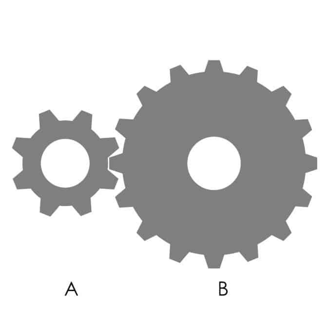
Consider two gears A and B as shown in the figure above. Gear A has 8 teeth and Gear B has 16 teeth. When Gear A rotates one complete revolution, all 8 teeth return to their starting position. During this rotation, those 8 teeth of Gear A engage with 8 teeth of Gear B. Since Gear B has 16 teeth total, an additional complete revolution of Gear A is required to engage the remaining 8 teeth of Gear B. Therefore, Gear A must rotate twice to produce one complete revolution of Gear B. The RPM of Gear A is twice the RPM of Gear B, and the RPM of Gear B is half the RPM of Gear A.
When motion transmits from a smaller device to a larger device, RPM reduces. When motion transmits from a larger device to a smaller device, RPM increases.
Practical Example:
In a rickshaw system, the sprocket pulled by the rider is larger than the sprocket attached to the rear tire. Motion transmits from the larger sprocket to the smaller sprocket, and the RPM increases to drive the wheel at a higher rotational speed than the pedalling cadence.
Driver and Driven:
The device that transmits motion to another device is the driver. The device that receives motion is the driven. In the figure above, Gear A is the driver and Gear B is the driven.
To increase RPM, the driver must be larger than the driven. To decrease RPM, the driver must be smaller than the driven.
Common Terms Used in Yarn Manufacturing
Modern ring spinning frames operate with spindle speeds reaching up to 25,000 RPM. Early ring frames in the 1870s achieved only 5,000-7,500 RPM. The Rabbeth spindle design of the 1880s enabled speeds exceeding 7,500 RPM without vibration. Modern machines accommodate up to 1,824 spindles per frame, with mechanical doffing systems completing a doffing cycle in 30-35 seconds.
Draft Change Pinion (D.C.P.)
The Draft Change Pinion (D.C.P.) changes the draft of a machine by altering the teeth number or size of the pinion. D.C.P. devices are typically gears or pinions. Draft is the ratio of the surface speed difference between the back roller and front roller, expressed as a numerical ratio typically ranging from 1.0 to 2.5 in cotton spinning applications.
Why Front Roller RPM Remains Stable During Draft Changes
- The front roller speed directly determines the production rate of the machine.
- During draft changes, the production must remain uninterrupted.
- Draft changes occur by adjusting the back roller RPM while maintaining front roller RPM.
The draft changes when the difference of RPM between the front roller and back roller increases or decreases. When the RPM difference increases, draft increases. When the RPM difference decreases, draft decreases. The D.C.P. must be positioned between the front roller and back roller to achieve this. The D.C.P. can be at the driver position or the driven position relative to the back roller.
Parameters for Increasing and Decreasing Draft
When draft increases, the back roller RPM must decrease. To achieve this:
- If the D.C.P. is in the driver position, decrease the size of the D.C.P.
- If the D.C.P. is in the driven position, increase the size of the D.C.P.
This configuration reduces the RPM of all subsequent gears and rollers, ultimately decreasing the back roller RPM and increasing the draft.
When draft decreases:
- If the D.C.P. is in the driver position, increase the size of the D.C.P.
- If the D.C.P. is in the driven position, decrease the size of the D.C.P.
In this case, motion transmits from the front roller to the back roller, and the back roller RPM increases to reduce the draft.
Twist Change Pinion (T.C.P.)
The Twist Change Pinion (T.C.P.) changes the twist of the product per unit length by altering its teeth number or size. Twist is imparted by the differential between the spindle speed and the front roller delivery speed. The spindle speed typically ranges from 8,000 to 25,000 RPM in modern ring spinning frames. Since the spindle speed remains constant during twist adjustments, the front roller delivery speed changes to alter the twist level.
The T.C.P. must be positioned between the spindle and the front roller so that changing the T.C.P. does not affect the draft.
To increase twist per unit length, the front roller delivery (RPM) must decrease. When the T.C.P. is in the driver position, decrease its size. When the T.C.P. is in the driven position, increase its size.
To decrease twist per unit length, the front roller delivery (RPM) must increase. When the T.C.P. is in the driver position, increase its size. When the T.C.P. is in the driven position, decrease its size.
When the T.C.P. changes, the RPM of gears and corresponding rollers downstream also change, including both the back and front rollers. However, since the RPM of both rollers changes by the same ratio, the draft remains unaffected—only the front roller delivery changes.
Since the RPM of both back and front rollers change by the same ratio when the T.C.P. is adjusted, the draft remains constant. Only the front roller delivery changes, which directly controls the twist per unit length.
Gear Ratio and Pinion Settings Quick Reference
| Configuration | Driver Size | Driven Size | RPM Result |
|---|---|---|---|
| Gear Train 1 | 8 teeth | 16 teeth | Driven = 50% of Driver RPM |
| Gear Train 2 | 16 teeth | 8 teeth | Driven = 200% of Driver RPM |
| 1:1 Transfer | Same shaft | Same shaft | Same RPM (transfer, not transmission) |
D.C.P. and T.C.P. Quick Settings Guide
| Action | D.C.P. Driver Position | D.C.P. Driven Position | T.C.P. Driver Position | T.C.P. Driven Position |
|---|---|---|---|---|
| Increase Parameter | Increase D.C.P. size | Decrease D.C.P. size | Increase T.C.P. size | Decrease T.C.P. size |
| Decrease Parameter | Decrease D.C.P. size | Increase D.C.P. size | Decrease T.C.P. size | Increase T.C.P. size |
Note: D.C.P. controls draft (back roller RPM). T.C.P. controls twist (front roller delivery). Both are positioned between rollers to affect downstream components without disrupting the other parameter.
Key Parameters in Ring Spinning
| Parameter | Typical Range | Unit |
|---|---|---|
| Ring Frame Spindle Speed | 8,000 – 25,000 | RPM |
| Draft Ratio (Cotton) | 1.0 – 2.5 | Ratio |
| Twist per Inch (Typical) | 8 – 25 | TPI |
| Front Roller Diameter | 25 – 50 | mm |
| Back Roller Diameter | 25 – 50 | mm |
| Machine Capacity (Modern) | Up to 1,824 | Spindles/frame |
| Doffing Time (Modern) | 30 – 35 | Seconds |
References
- Wikipedia. (2025). Ring Spinning. Wikimedia Foundation.


